From virtual to physical model
AKKONDesk operates with DIN G-Code. DIN G-Code is a unique language that was especially developed for controlling CNC machines. Usually control commands are saved in text files and will be interpreted by a CNC controller. Based on that information the CNC controller create the control siganls for the motors, cooling system, milling spindle etc. Altough CNC easy CNC programs can be programmed manually today there is a wide spectrum of software availabe that creates G-Code. Based on CAD (Computer Aided Drawing) modles a CAM (Computer Aided Manufacturing) software calculates the G-Code that will be used by the CNC controller. Figure 3 shows the process from the virtual to the physical model.
This is an example page. It’s different from a blog post because it will stay in one place and will show up in your site navigation (in most themes). Most people start with an About page that introduces them to potential site visitors. It might say something like this:
Figure 3: From virtual to physical model
CAD-modell (graphical model)
A CAD model represents the geometry and properties e.g. used materials in a computer readale format. Well known professional vector oriented CAM programs are e.g. AUTOCAD, EUCLID, CATIA or PRO-ENGINEER. But there is also a wide rage of vector oriented graphics programs like e.g. Corel Draw that can also be used for creating 2D, 2-1/2D and 3D models. Most of the programs have som exporting filters that can save the models in DXF or HPGL format.
CAM-model
Based on the CADmodel the CAM software converts geometrical an dmaterial data of the CAD model to the cutting path and control command for the cooling system, vacuum clearner, milling spindle or milling feed.
CNC-model
Based on CAM model the CNC processor generates signals for controlling the machine hardware.
Hardware requirements
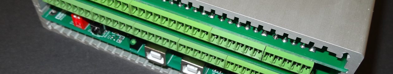
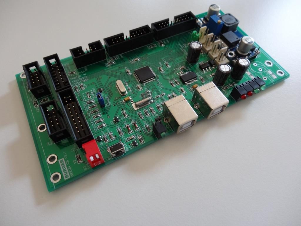
As direct access and also real time procssing to computer periphery is limited under MS Windows XP™ AKKON CNC works on the client server principle. All tasks, that requires user input can be done over AKKON Desk (client) under MS Windwos. AKKON Desk is connected over USB or a serial connection to the AKKON USB controller and sends control commands. The AKKON USB controller generates control signals for the machine hardware. Figure 4 shows a screen shot of the two different AKKON Controllers Boards.
For operation AKKON requires a personal computer with Pentium processor > 1GHz and operating system MS Windows™ (2000, Windows XP or Windows VISTA)
Typical applications with AKKON
- Milling machines
- Laser- and plasma cutting machines
- Machines with 1-4 axis control
- Pick & Place tasks
- Lathes
- Engraving
Supported G-Code (and M-Code)
AKKON supports most of the G- and M-Codes that are necessary for producing 2-1/2D geometries. Figure 5 outlines an overview of the most important supported G- and M-Codes.
Downloads AKKONDesk CNC software
Link Project Description Date Comment AKKON CNC CNC software installer for MS-Windows, Version 2.0.0.832 25.2.2019 AKKON Desk CNC Software - inkl. Beta-Version mit USB-Treiber AKKON CNC CNC software installer for MS-Windows, Version 2.0.0.806 8.11.2018 AKKON Desk CNC Software - inkl. Beta-Version mit USB-Treiber
AKKON CNC TN007 Dokumentation unterstützte G-Codes 1.11.2017 
AKKON CNC TN007 Documentation Supported G-Code 1.11.2017 AKKON CNC TN014 firmware update 1.11.2017 AKKON CNC TN015 AKKON CNC system datasheet 1.11.2017 AKKON CNC TN016 Hardwaretest AKKON USB controller 1.11.2017 AKKON CNC TN017 setup AKKON simulator 1.11.2017 AKKON CNC TN019 Using CorelDraw with AKKON CNC 1.11.2017 AKKON CNC TN020 additional features 1.11.2017 AKKON CNC TN022 AKKON CNC
Quickstart1.11.2017 AKKON CNC TN022 AKKON CNC Schnellstart 1.11.2017 AKKON CNC TN024 CNC-connection 1.11.2017 AKKON CNC TN029 configuration procedure 1.11.2017 Includes information about limit switch, referencing procedure and manual movement configuration