The XMCIO 2Go board is designed as an extension to the Infineon XMC 2 Go evaluation board. The board provides some protected inputs and outputs, a stepper motor interface as well as various assembling options for power supply and easy mounting.
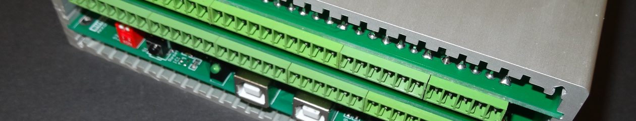
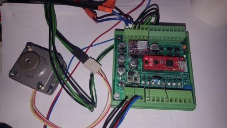
Picture 1 shows a standard setting of the XMCIO 2Go board with vertical connectors mounted on DIN-rail case.
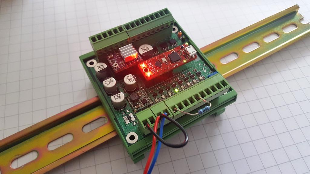
Picture 1: XMCIO 2Go board on DIN rail
Hardware
Depending on assembling the XMCIO 2Go board can be used with many configurations, .
Overview
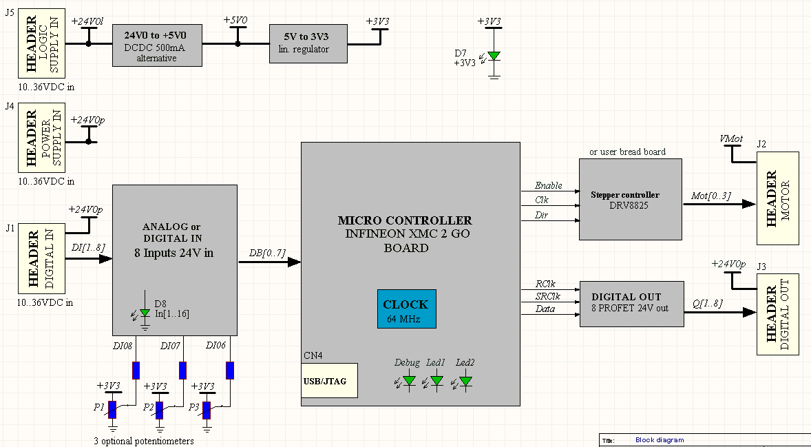
Picture 2: Block diagram of XMCIO 2Go board
Functionality and power supply
Generally, power supply of the XMCIO 2Go board is divided in power supply for logic, IO and stepper motor. However, depending on use, the power supply can be consolidates up to one supply.
Power logic: Depending on assembling, power for logic can be between 5 VDC to 24 VDC. The circuit is equipped with an internal 200 mA PTC resettable fuse.
Power IO: Is used for digital inputs and outputs. The circuit should be protected by an external fuse. Typical voltage levels are between 9 VDC to 32 VDC.
Power Motor: Depending on the used hardware respectively application, power supply can be up to 36 VDC. The circuit should be protected by an external fuse.
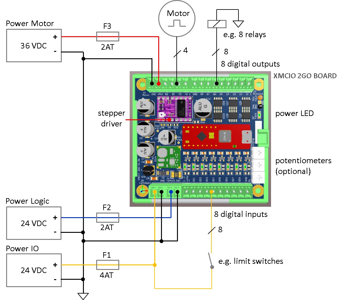
Picture 3: Power supply concept for XMCIO 2Go board
Common
All available IOs can be accessed with 3,81 mm PCB connectors. E.g. MC 1,5/2-ST-3,81 or MC 1,5/2-ST-3,81 type from PhoenixContact or similar connectors from many other suppliers.
Communication
Communication can be done over virtual UART (USB to RS232) directly over XMC 2Go evaluation board.
Digital inputs and alternative functionality
Eight digital inputs with over- and under-voltage protection and status led are available. Three inputs can alternatively be used as analogue inputs.
Furthermore three additional potentiometers can be assembled on the board e.g. for easy parametrization of an application. IOs can also be configured for use as SPI or UART interface.
Digital outputs
Eight digital outputs operating from 5 to 36 VDC power supply with current limitation, overload protection, over-voltage protection, short circuit protection, ESD protection and thermal shutdown are on board. The outputs are able to drive small ohmic and inductive loads e.g. small relays up to 200 mA per output.
Stepper motor interface
One stepper motor interface can be used with standard low-cost stepper motor driver from Pololu DRC8825. The stepper motor interface supports ENABLE, DIRECTION and CLOCK signals. CLOCK signal can be created by PWM-hardware of the XMC 2Go board or fully by software.
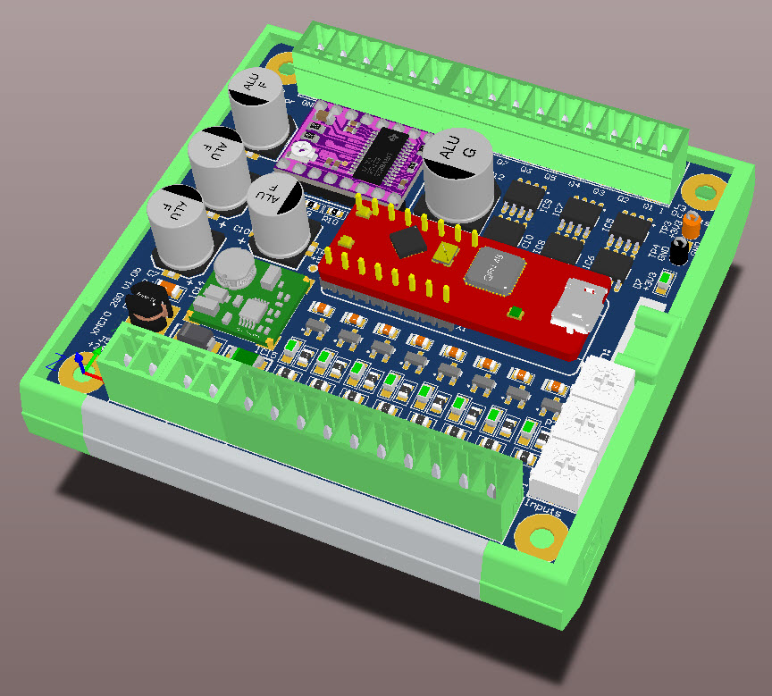
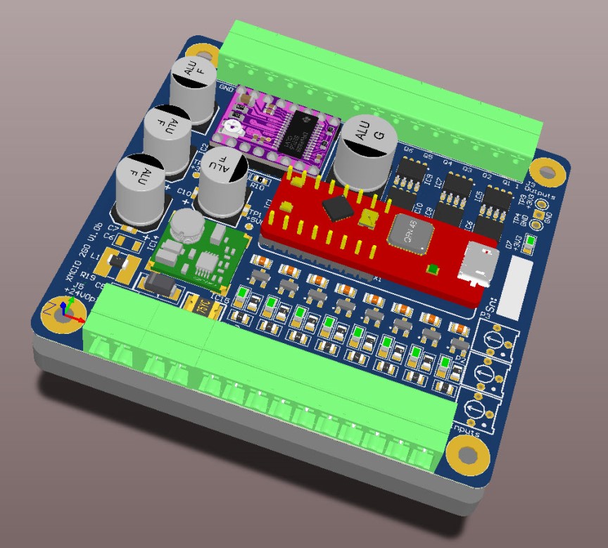
Picture 4: XMCIO 2Go with stepper interface
The interface can alternatively be use for
- one stepper interface for driving stepper motor cards
- general purpose IO with (one IO can be used as hardware interrupt input)
- small bread boards with user specific electronics
Mechanical
The board can easily be used with different available 72 mm DIN-Rail cases, e.g. from PhoenixContact, or mounted in any case using four assembling holes. The PCB supports vertical (for DIN-rail cases) and horizontal connectors (e.g. for mounting the board on a plate).
Picture 5: XMCIO 2Go mounted on DIN rail case (left), XMCIO 2Go mounted on a plate (right)
Dimensions
Length: 78.25 mm
Width: 72.0 mm
Total height with connectors from top of PCB: around 19 mm
Software development
Development can be done with free IDE called Dave 4, provided by Infineon or e.g. gcc tools using Eclipse IDE.
The downloads includes a basic libray for easy initialization and use of the available hardware as well as some basic examples outlining the functionality of the hardware and for easier start-up.
Important
Diode D1 has to be desoldered from XMC 2Go board before use if USB connector is connected to USB master.
Downloads
Please see download section.
History
Hardware version: 1.0b
Date: September 2018