Product area |
|
| Navigation |
| Home |
| Product area |
| Automation |
| CNC |
| CNC
gallery |
| Hobby |
| CNC-Machine |
| Tutorials |
| My shop floor |
| Misc |
| Feedback |
| Contact |
| 4 AKKON CNC | ||||||||||||||||||||||||||||||||||||||||||||||||||||||||||||||||||||||||||||||||||||||||||||||||||||||||
|
||||||||||||||||||||||||||||||||||||||||||||||||||||||||||||||||||||||||||||||||||||||||||||||||||||||||
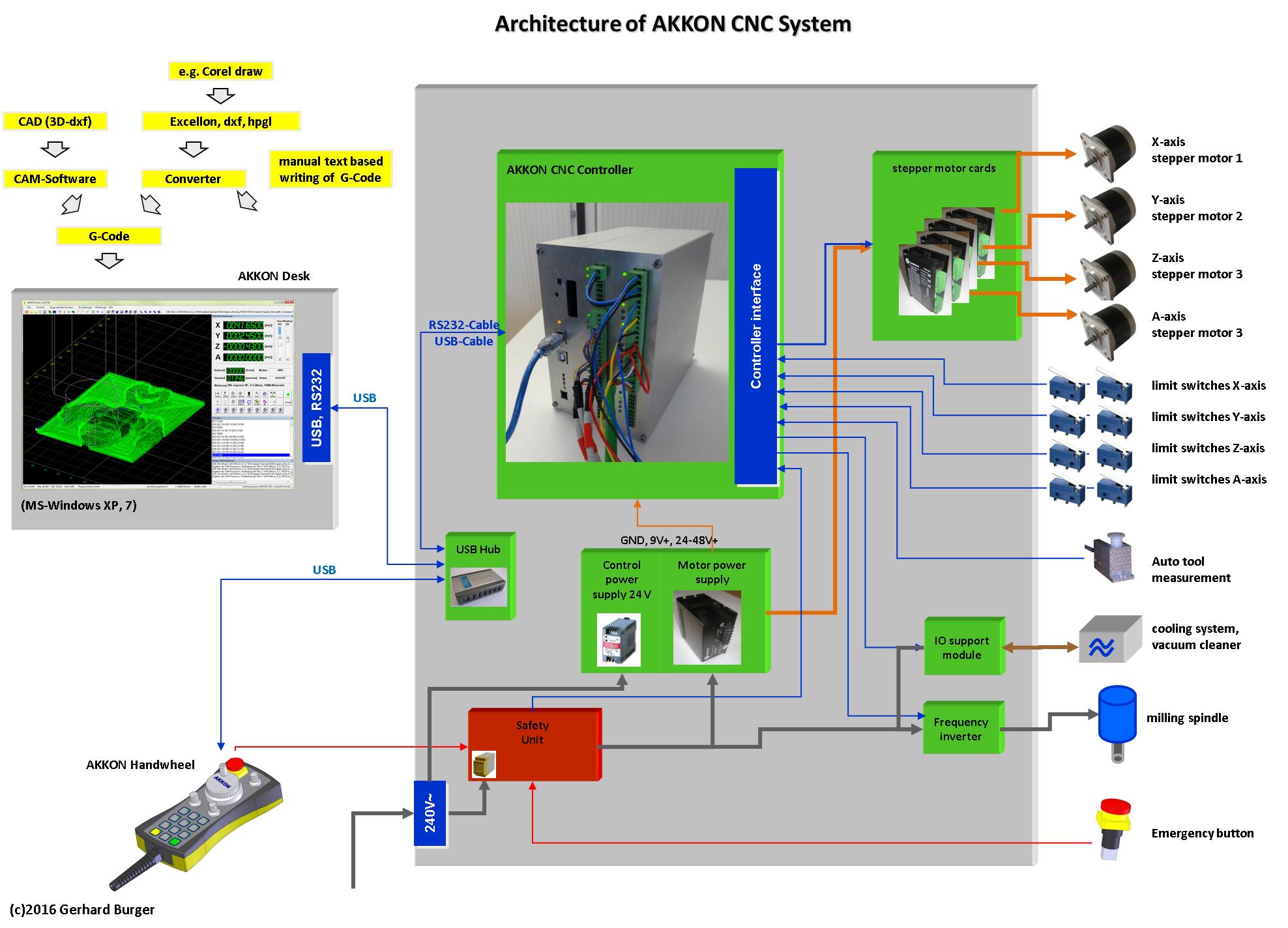
move to Download of AKKONDesk4.1 IntroductionAKKON is a CNC (Computer Numeric Control) software for controlling 2D- and 2-1/2D machines working with G-Code based on DIN 66025. The prgram works in cooperation with the AKKON USB controller board. AKKON Desk read CNC-Code and sends it to the AKKON USB controller. The AKKON USB Controller generates contol signal for the machine hardware. The concept is shown in figure 2. The application operates in a manual and an automatic mode. The screen shot above shows the user interface of AKKON Desk. Figure 1: Principle architecture of CNC control by AKKON CNC 4.2 Funktionality of AKKON
With optional hardware a AC-motor can be controlled by the AKKON USB Controller. This project is currently under construction and will be available for free. 4.3 From virtual to physical modelAKKON operates with DIN G-Code. DIN G-Code is a unique language that was especially developed for controlling CNC machines. Usually control commands are saved in text files and will be interpreted by a CNC controller. Based on that information the CNC controller create the control siganls for the motors, cooling system, milling spindle etc. Altough CNC easy CNC programs can be programmed manually today there is a wide spectrum of software availabe that creates G-Code. Based on CAD (Computer Aided Drawing) modles a CAM (Computer Aided Manufacturing) software calculates the G-Code that will be used by the CNC controller. Figure 3 shows the process from the virtual to the physical model.
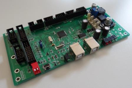
Figure 3: From virtual to physical model CAD-modell (graphical model)A CAD model represents the geometry and properties e.g. used materials in a computer readale format. Well known professional vector oriented CAM programs are e.g. AUTOCAD, EUCLID, CATIA or PRO-ENGINEER. But there is also a wide rage of vector oriented graphics programs like e.g. Corel Draw that can also be used for creating 2D, 2-1/2D and 3D models. Most of the programs have som exporting filters that can save the models in DXF or HPGL format. CAM-modelBased on the CADmodel the CAM software converts geometrical an dmaterial data of the CAD model to the cutting path and control command for the cooling system, vacuum clearner, milling spindle or milling feed. CNC-modelBased on CAM model the CNC processor generates signals for controlling the machine hardware. 4.4 Hardware requirementsAs direct access and also real time procssing to computer periphery is limited under MS Windows XP™ AKKON CNC works on the client server principle. All tasks, that requires user input can be done over AKKON Desk (client) under MS Windwos. AKKON Desk is connected over USB or a serial connection to the AKKON USB controller and sends control commands. The AKKON USB controller generates control signals for the machine hardware. Figure 4 shows a screen shot of the two different AKKON Controllers Boards.
For operation AKKON requires a personal computer with Pentium processor > 1GHz and operating system MS Windows™ (2000, Windows XP or Windows VISTA) 4.5 Typical applications with AKKON
|

 click image to enlarge


| G-/ M-Code | Description | Remarks |
|---|---|---|
| M03 | Spindle on | |
| M05 | Spindle off | |
| M06 | change tool position | |
| M08 | cooling system on | |
| M09 | cooling system off | |
| M30 | program end | |
| G00 | fast linear interpolation | |
| G01 | linear interpolation | |
| G02 | arc clockwise | |
| G03 | arc anti-clockwise | |
| G20 | geometrical values in inches | |
| G21 | geometrical values metric | |
| G40 | tool correction of | |
| G41 | tool radius correction left side | partly implemented (most CAM tools do this job) |
| G42 | tool radius correction right side | partly implemented (most CAM tools do this job) |
| G54-G59.3 | select work piece (9 work pieces) | |
| G66 | engrave text | |
| G67 | set font style | |
| G68 | set text direction | |
| G69 | set text height | |
| G70 | set user defined font | |
| G74 | set zero point of part | |
| G76 | move to machine zero point M0 | |
| G77 | moce to tool change position T0 | |
| G79 | drill cycle on position | |
| G81 | define drill cycle | |
| G90 | use absolute coordinates | |
| G91 | use incremental coordinates |
Figure 5: Table of supported G- and M-Codes (not
complete)
Example of a small Program using Fonts
The follwowing example shows a manually written CNC-program in G-Code and the output. Figure 6 outlines the CNC program in G-Code. The program is witten in a text file editor.

Figure 6: Easy CNC-program written in notepad and output on AKKON
Desk
During programming, the output can easily be viewed with the freeware program CNC-viewer (figure 7).

Figure 7: Simulation output of the example program "Sextant.txt"
After processing the data on the AKKON CNC-Controller using the simulation mode, the output is as follows:
 click
image to enlarge
click
image to enlarge
Figure 8: Output of example program on AKKON Desk (USB)
4.7 Beta test
AKKON CNC is currently in a beta phase. The hardware is currently available as self assembly kit for a reduced price. Please, let me know if you are interested The CNC software is only running with the pre programmed boot loader that is placed on the AKKON USB controller board. Firmware updates can easily be done be the user. During the beta phase AKKON CNC is free for use. During beta test I can also provide some technical support.
4.9 Downloads
|
Version 1.0, ©Gerhard Burger 2004-2016, all rights reserved, last update 25.10.2016 |